Our Offerings
- Checking systems to ensure all component are present or not before dispatch
- Checking of all components to ensure proper locations & Orientations
- Checking of components with Base Material & Colors
- LED Displays that monitor presense/absense of child components in final assembly
- Operations with Two hand Safety
- Interlock for component rejections
- OK / Dot Hot punch for passed component
- Component tracking system with bar code and/or color stickers

Today, this concept is in wide use in Japan. Toyota Motor Corporation, whose production system Shingo helped design, averages twelve poka-yoke devices per machine in their manufacturing plants, thus validating the concept as beneficial to industry.
Potential benefits are:
-
 elimination of set-up errors and improved quality
 -
decreased set-up times with associated reduction in production time and improved production capacity
-
simplified and improved housekeeping
-
increased safety
-
lower costs
-
lower skill requirements
-
increased production flexibility
-
improved operator attitudes.
TYPES OF POKA-YOKES | As Listed in http://www.referenceforbusiness.com Click Here To Read More
Poka-yoke is based on prediction and detection. That is, recognizing that a defect is about to occur or recognizing that a defect has occurred. Consequently, there are two basic types of poka-yoke systems. The control poka-yoke does not allow a process to begin or continue after an error has occurred. It takes the response to a specific type of error out of the hands of the operator. For example, a fixture on a machine may be equipped with a sensing device that will not allow the process to continue unless the part is properly inserted. A 3.5-inch floppy disk will not work if inserted backwards or upside down. As a matter of fact, it won't fit into the drive at all unless properly inserted. A second type of poka-yoke provides some type of warning when an error occurs. This does not prevent the error, but immediately stops the process when an error is detected. This type of poka-yoke is useful for mass production environments with rapid processing as the device prevents mass production of scrapped material. For environments where large losses of time or resources do not result, a warning poka-yoke is warranted. All that is needed is a way to ensure that the error is investigated and corrected in a timely manner.
Poka-yokes can be as simple as a steel pin on a fixture that keeps incorrectly placed parts from fitting properly, or they can be as complex as a fuzzy logic neural network used to automatically detect tool breakage and immediately stop the machine. Surprisingly, the simple low-cost devices tend to be in the majority. Regardless of degree of simplicity, all poka-yokes fall into one of three categories: contact methods, fixed-value methods, and motion-step methods. Each is briefly discussed.
EXAMPLES. | As Listed in http://www.referenceforbusiness.com Click Here To Read More
A number of "real world" applications are presented in the business and engineering literature. Below are a list of examples of poka-yoke applications. James R. Evans and William M. Lindsay present these examples in their book The Management and Control of Quality:
- Color-coding a wiring template to assist the worker.
- Installing a device on a drill to count the number of holes drilled in a work piece; a buzzer sounds if the work piece is removed before the correct number of holes has been drilled.
- Cassette covers were frequently scratched when the screwdriver slipped out of the screw slot and slid against the plastic covers. The screw design was changed as shown in Table 1 to prevent the screwdriver from slipping.
- A metal roller is used to laminate two surfaces bonded with hot melted glue. The glue tended to stick to the roller and cause defects in the laminate surface. An investigation showed that if the roller were dampened the glue would not stick. A secondary roller was added to dampen the steel roller during the process, preventing the glue from sticking.
- One production step at Motorola involves putting alphabetic characters on a keyboard, then checking to make sure each key is placed correctly. A group of workers designed a clear template with the letters positioned slightly off center. By holding the template over the keyboard, assemblers can quickly spot mistakes.
John Grout presented these examples in "Mistake-Proofing Production," an article written for Production and Inventory Management Journal:
- Trinity Industries Railcar Division workers created a layout jig to avoid having to use a tape measure and chalk to position subassemblies on each car individually. The jig has tops that allow it to be quickly positioned correctly on the car's chassis. Each component that is to be attached to the car has a corresponding cutout on the jig. The jig eliminates two modes of worker error. It eliminates incorrect measurements and inaccurate positioning of parts. It also eliminates the worker vigilance required to ensure all of the components are attached. Omitted parts are made very obvious because an empty space exists on the layout jig. Without the jig, there would be no indication that anything is missing. Once parts are spot welded in place the jig is lifted off and welding is completed. Not only is dependence on worker vigilance reduced, cost savings result from the simplified, accelerated process.
- Binney and Smith, maker of Crayola Crayons, uses light sensors to determine if each crayon is present in each box of crayons they produce. If a crayon is missing, the machines will stop automatically. Producing complete boxes of crayons right the first time is the preferred outcome.
- A mail-order computer company has designed its boxes and packing material to avoid mistakes. The inner flaps of the box bottom have a large brightly colored warning to "Stop! Open the other side." When the correct side is opened, a book titled "Setting Up Your Computer" is on top of the packing material. The sequence of the book matches the arrangement of the contents of the box. Each instruction involves the next item from the box.
- Airplane lavatory lights come on only when the door lock is engaged. This keeps customers from failing to lock the door.
- John Deere produced a gearbox that was assembled without oil, mounted on a machine, and required replacement after factor tests. A team streamlined production with a simple proximity switch that opens after all components were loaded into an assembly fixture. The switch prevents workers from using air wrenches to tighten bolts on the assembly until they cycle an oil gun into the gearbox. After filling the gearbox a solenoid releases the interlock sending air to the wrench. Then workers can tighten cover bolts and send the box to the next station.
- The electrical connectors in one machine control formerly used only three-pin connectors to join each in a series. Labels instructed assemblers which boards went where and which connectors should be joined. But in the field, assemblers connecting and disconnecting them wear or bend the pins, which meant putting on a new plug. Soon the label was gone. The simple solution involved three, four and five-pin connectors that cannot join others and demand a single assembly sequence.
- Ficarra's solution to labels that come off is to machine them into parts, especially when the function is to determine the correct orientation.
- On Varian machines, assemblers are guided by small machined-in pictures that cannot wear off.
 Due to Our Products & Services we provide to our customers with excellent Quality & Safety standards for manufacturing hydraulic presses/ Hydro Pneumatic / Pneumatic Press Due to this capability & to suit our customer’s Standard & Custom requirements and specifications, In a relatively short span of time which have become a name to Vimal Industrial System
  Punching operations in Door Trims


 Crank shaft assembly
 Rugged Design/ well designed structures


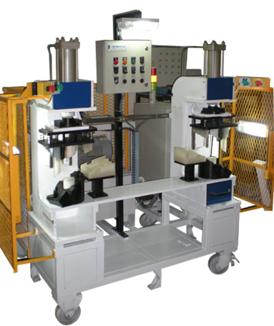
 The parts to be welded are pressed on preheated plate for predefined time for sufficient plastic material to melt. Then the heated plate is withdrawn and the slightly melted surface of two parts is pressed together to form a joint. Plastic welding using hot plate welding is useful where plastic parts have complex geometries, like curved surfaces and internal walls or any irregular shapes. This process is employed where both high strength joints and hermetic seals are required.